Electric Circuits: Current, Voltage, Resistance
Begin
14 pages · ~28 min
Electric Circuits: Current, Voltage, Resistance
Basic introduction to electric circuits covering current, voltage, and resistance for beginners.
What you’ll learn
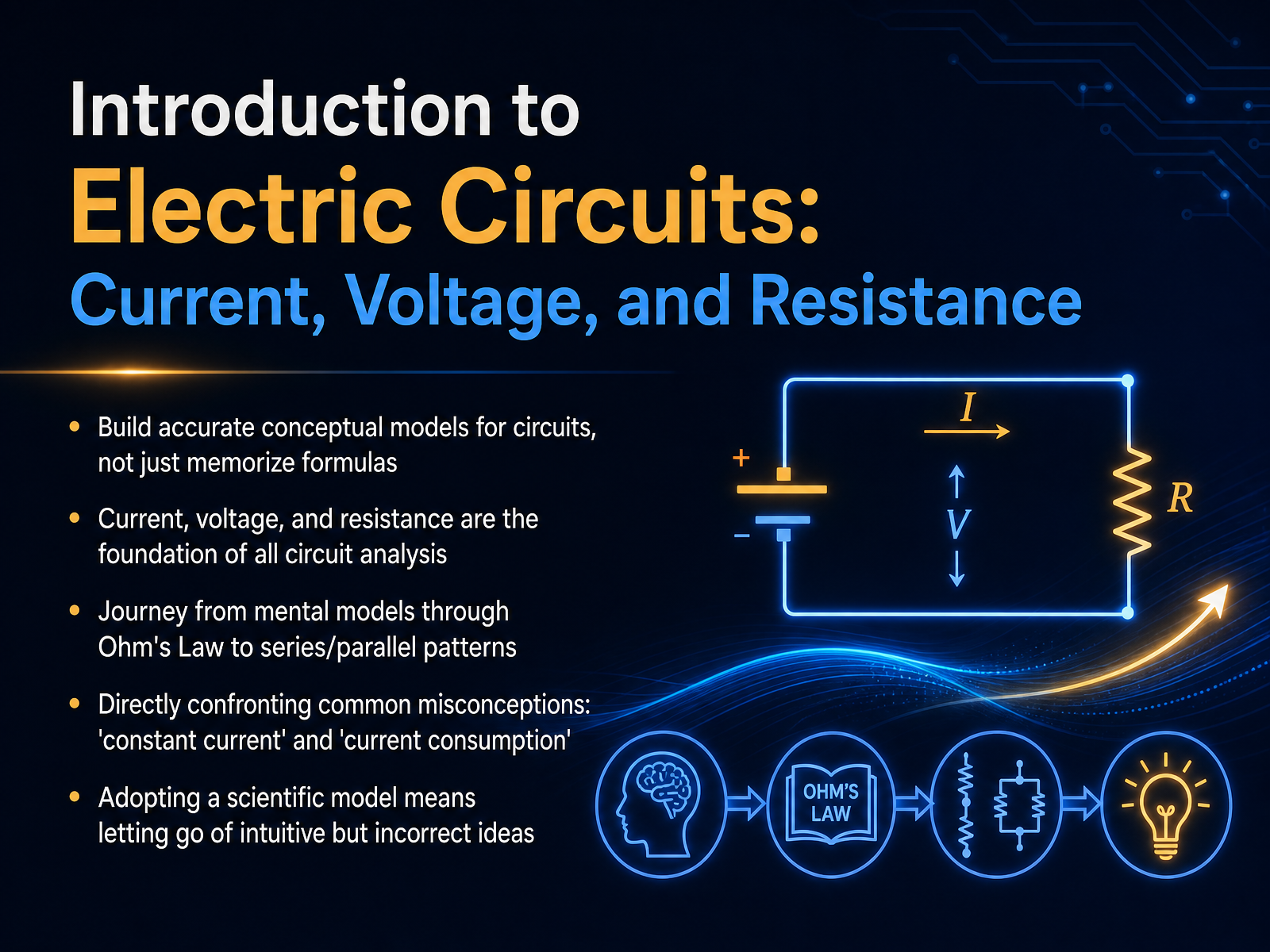
- 01Introduction to Electric Circuits: Current, Voltage, and ResistanceWelcome. In this course, we are going to build a real, working mental model of electric circuits. We are not just memorizing formulas. Instead, we will focus on three essential ideas: current, voltage, and resistance. Think of these three as the foundation for everything else you will learn in circuit analysis.
Our journey together will start with simple mental pictures. Then, we will connect those pictures to Ohm's Law, and finally, we will see how circuits behave in series and parallel patterns. Along the way, we will directly address some common traps. For example, many learners believe that a battery always provides a constant current, or that current gets used up as it travels through a circuit. These are intuitive ideas, but they are not scientifically accurate. Letting go of these incorrect assumptions is a big step toward adopting a true scientific model. So, let's get ready to clear up that confusion and build your understanding from the ground up.
Next, we will start by confronting the misconceptions we bring.zybooks.comphysicsclassroom.comdoi.org+22 min
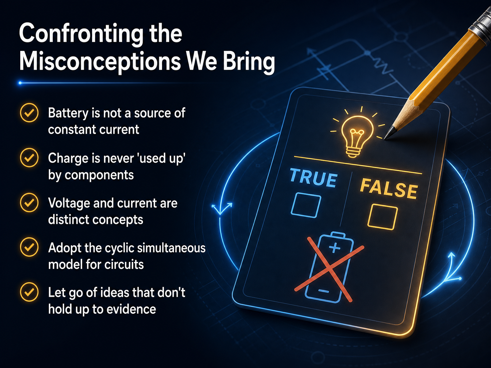
- 02Confronting the Misconceptions We BringNow, let's talk directly about some of the ideas we may bring with us to this topic. These are common and perfectly logical, but they often don't hold up when we test them. First, it's a mistake to think of a battery as a source of constant current. A battery actually provides a constant push—a voltage—and the circuit decides how much current flows as a result. Another very common idea is that charge gets 'used up' by components like a light bulb. In reality, charge is never consumed; it simply flows in a complete loop. The energy is transferred, but every single charge that leaves one side of the battery returns to the other. We also need to clearly separate voltage and current. They are distinct concepts. Voltage is the push that drives the charges, and current is the resulting flow of those charges. They are not two words for the same thing. To make real progress, we need to let go of the idea that events happen one after another down a wire. Instead, we'll adopt a cyclic simultaneous model, where a change at any point affects the whole system at once. As we move forward, we'll test these old ideas against evidence, and if they don't fit, we'll be ready to replace them. Next, we'll establish the one non-negotiable rule: what a circuit absolutely needs.
 zybooks.comphysicsclassroom.comdoi.org+22 min
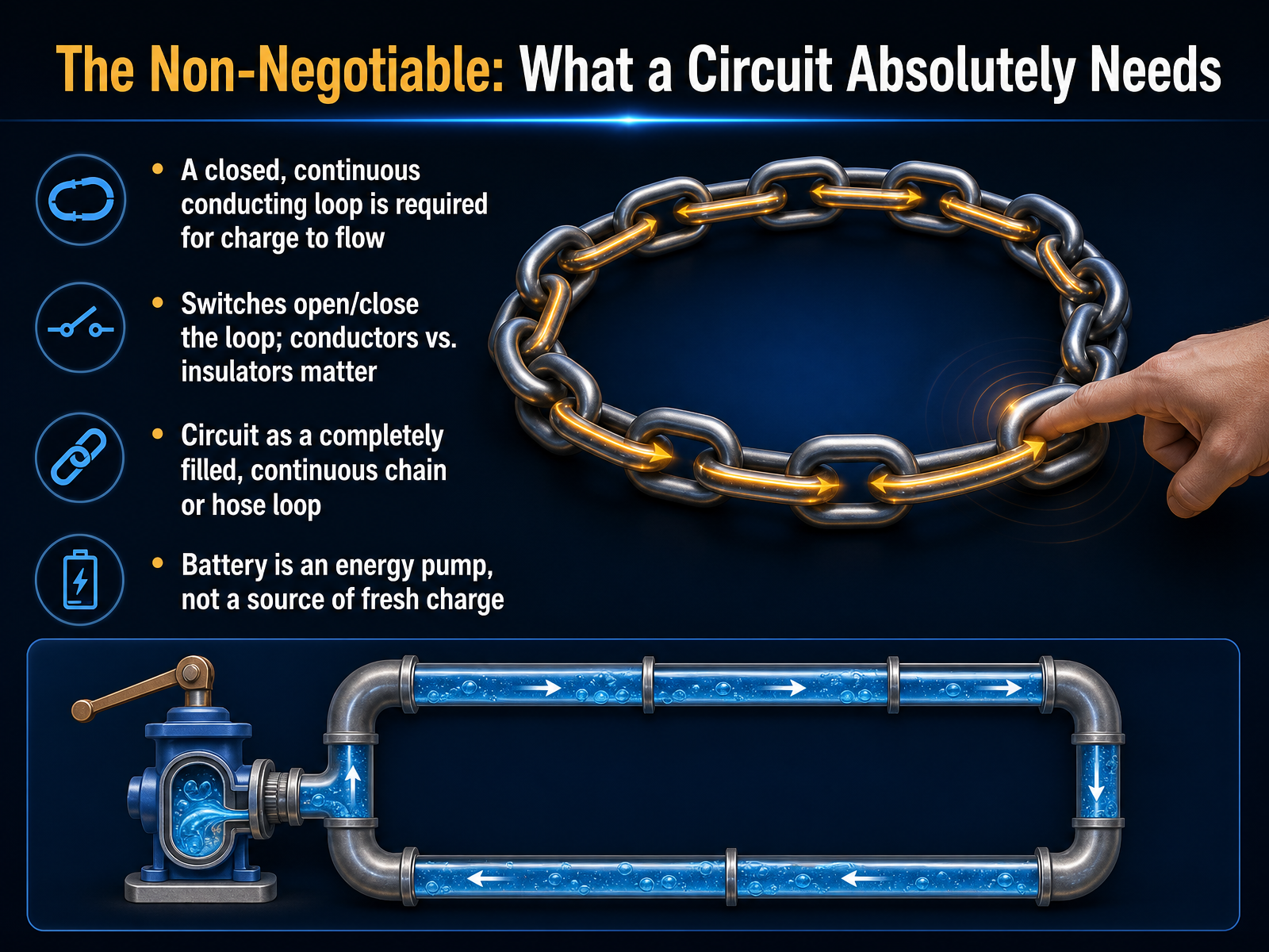
 - 03The Non-Negotiable: What a Circuit Absolutely NeedsNow, let's look at the one thing a circuit absolutely cannot work without. Think of it like a closed, continuous loop, similar to a completely filled hose or a chain. For charge to flow, the path must be unbroken, making a full circle from one side of the battery, through the components, and back to the other side. This is why a switch is so important. Opening a switch breaks that loop, cutting off the flow instantly. It also helps explain why the materials we use matter. Conductors, like the copper wires, are part of that continuous chain. But insulators, like the plastic coating around the wires, are not. They act as barriers to make sure the charge stays on the correct path. I want to emphasize one more critical point here: the battery is not a source of fresh charge. It doesn't inject new electrons into the wires. Instead, think of the battery as an energy pump. Its job is to take the charges already in the loop and push them, giving them the energy they need to move around the circuit. Understanding this closed-loop idea and the battery's role as a pump is a key foundation for what comes next: electric current, and the important fact that it's a cycle, not something that gets consumed.
 doi.orghyperphysics.gsu.edunpsm-kps.org+22 min
 - 04Electric Current: It's Not Consumed, It's a CycleNow, let's focus on current itself. A very common idea is that a circuit consumes electric current -- that it gets used up by a light bulb, for example. But that's not what happens.
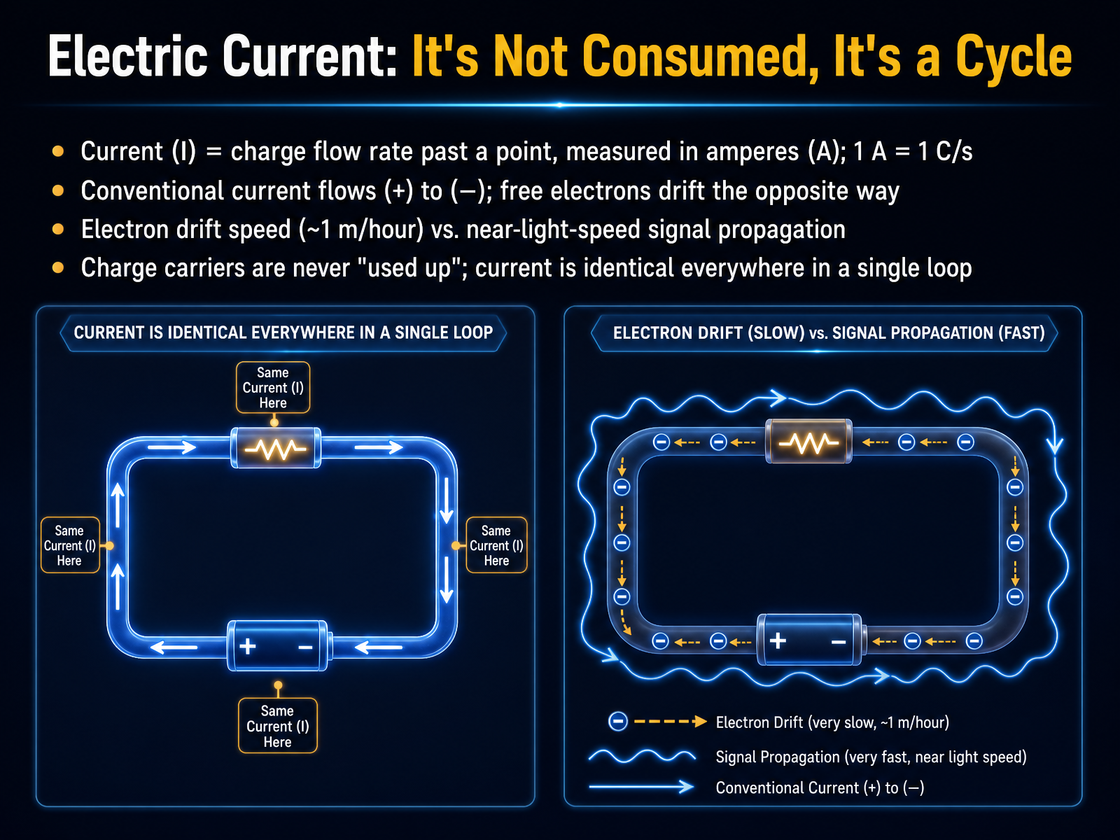
Think of electric current as a cycle, not a one-way trip that ends. Current, which we represent with the letter I, is simply the flow rate of charge. It's how many charged particles move past a point in the wire each second. We measure this in amperes, or amps for short. One amp means one coulomb of charge passes by in one second.
To picture the flow itself, we use the idea of conventional current -- a flow from the positive terminal to the negative terminal. In a metal wire, the actual free electrons drift the opposite way, from negative to positive. But here's the key: the electrons themselves are not consumed. They are already in the wire, and they move very slowly, perhaps only a meter per hour. What moves nearly at the speed of light is the signal, the push. That's why a light turns on instantly.
Because charge carriers are never used up, the current is exactly the same at every point in a single loop. What flows out of the battery must flow back in.
Next, we'll explore what causes this push: the concept of voltage, the reason for the push.
 en.wikipedia.orgopenstax.orgbipm.org+22 min
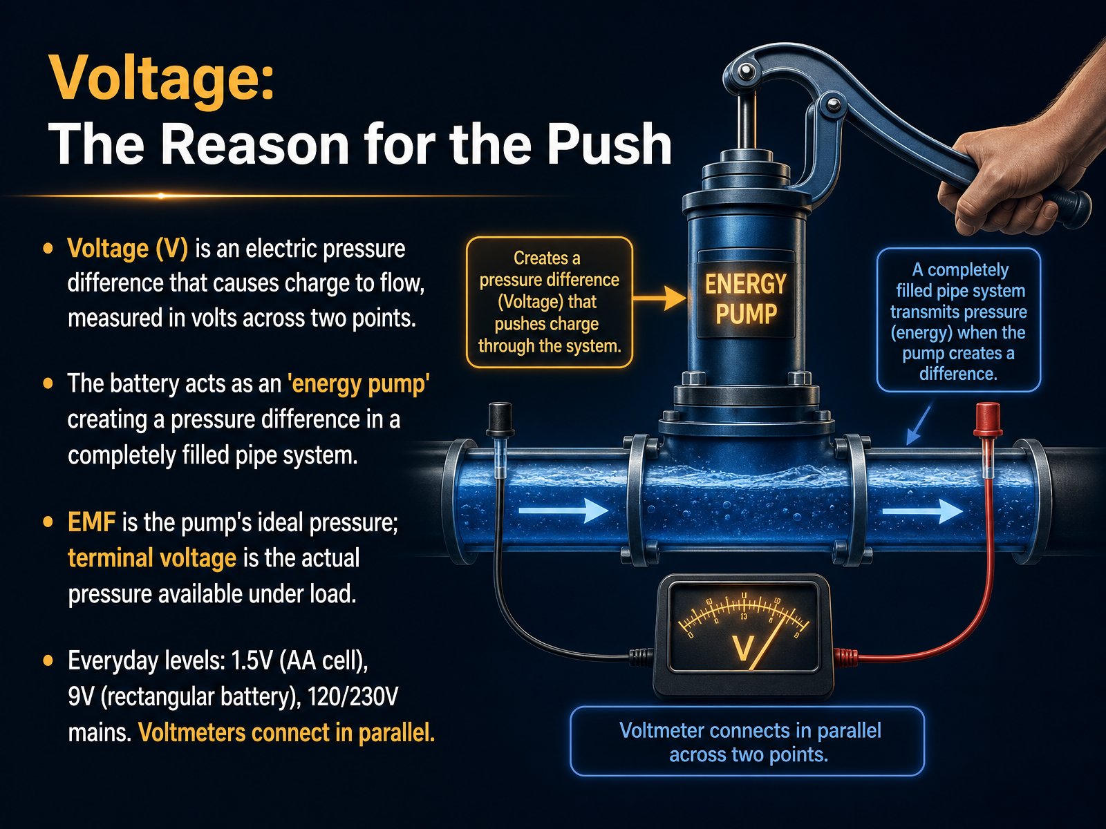
 - 05Voltage: The Reason for the PushLet's now focus on what actually causes charge to move in a circuit. We call this voltage. Think of voltage as an electric pressure difference between two points. Just like an air pressure difference pushes air through a hose, voltage difference pushes charge through a wire. In our closed loop, the battery acts like an energy pump. It takes in charge at low energy, gives it a boost, and sends it out at high energy. This pump creates the pressure difference in a completely filled pipe system. You might also hear two related terms: electromotive force, or E M F, and terminal voltage. E M F is the pump's ideal, maximum pressure. Terminal voltage is the actual pressure you get when the circuit is connected and working under load. In everyday terms, voltage comes in different sizes. A typical A A cell gives about one point five volts. A rectangular nine-volt battery gives, well, nine volts. And the power from your wall socket is usually one hundred twenty or two hundred thirty volts. To measure this pressure difference, we use a voltmeter, and we always connect it in parallel across the two points we want to check. So remember, voltage is the push that drives the flow. Next, we'll explore what opposes that push when we talk about resistance, the opposition to flow.
 doi.orghyperphysics.gsu.edunpsm-kps.org+22 min
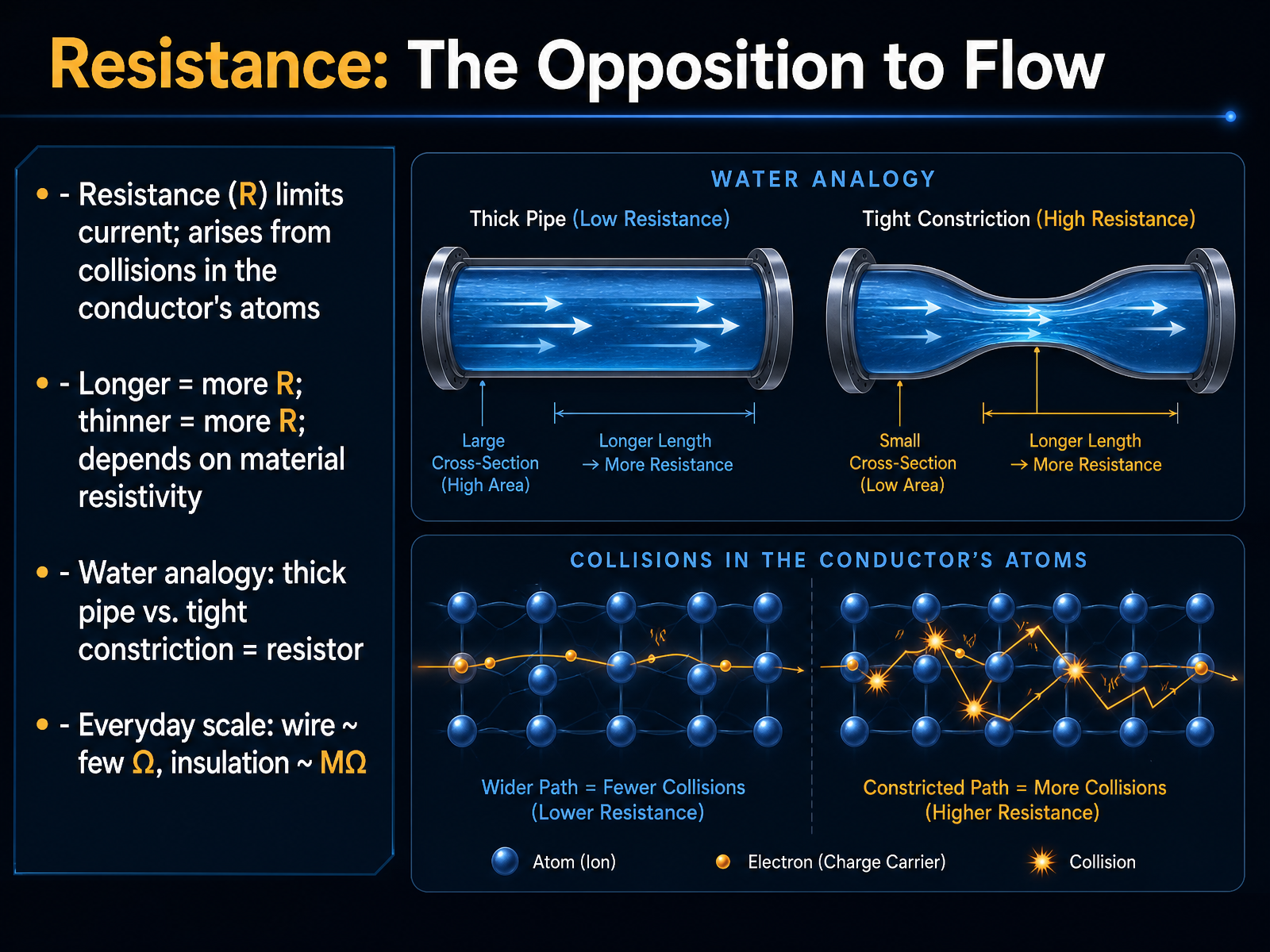
 - 06Resistance: The Opposition to FlowNow let's talk about resistance, which is simply the opposition to current flow. Inside a wire, electrons move through a material, and they bump into atoms along the way. Those tiny collisions create resistance, and they limit how much current can pass through. Think of it like a garden hose. A short, wide hose lets water flow easily. But a long, narrow tube makes the water push much harder to get through. Resistance works the same way. A longer or thinner conductor means more resistance. The material itself also matters. For example, a copper wire has very low resistance, just a few ohms. But the plastic insulation around it has extremely high resistance, millions of ohms, so current cannot escape. To sum it up, voltage pushes current, and resistance holds it back. Next, we'll see how these three quantities—voltage, current, and resistance—are united in one fundamental rule: Ohm's Law.
 doi.orghyperphysics.gsu.edunpsm-kps.org+22 min
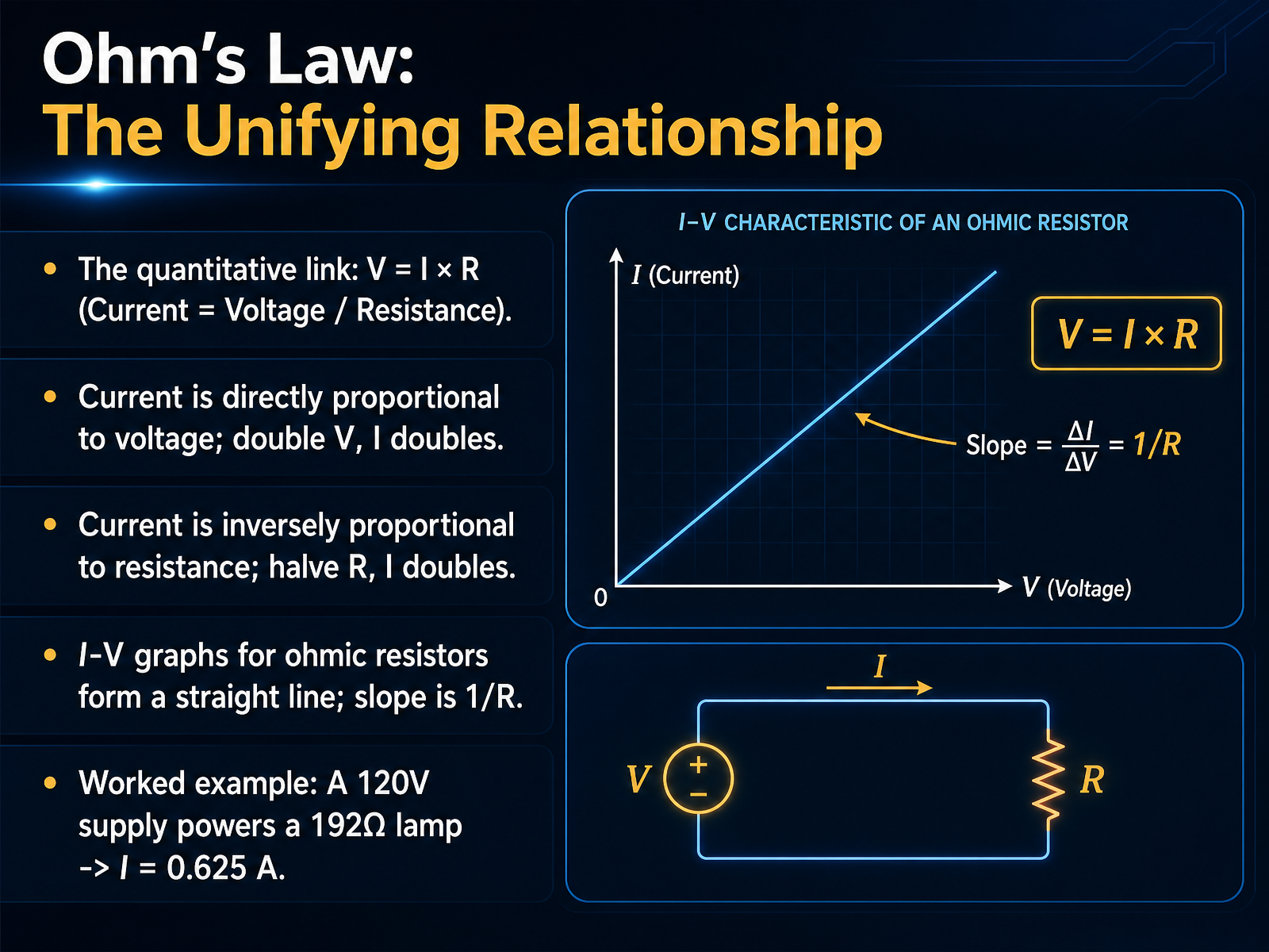
 - 07Ohm's Law: The Unifying RelationshipNow we can tie everything together with a simple, powerful equation: Ohm's Law. It says voltage equals current multiplied by resistance, or V equals I times R. A handy way to remember it is to think of current as voltage divided by resistance. This reveals two clear proportional relationships. First, current is directly proportional to voltage. If you double the voltage pushing on the circuit, the current doubles right along with it. Second, current is inversely proportional to resistance. If you make the resistance half as strong, you get double the current flowing through. When we plot current against voltage for a standard ohmic resistor, we see a straight line. The slope of that line is one divided by the resistance—a steeper slope means less resistance. Let's look at a quick example. A one hundred twenty volt supply powers a lamp with a resistance of one hundred ninety two ohms. Dividing the voltage by the resistance gives us a current of zero point six two five amps. That’s Ohm's Law in action. Next, we'll move from theory to practice in 'Getting Hands-On: Your Ohm's Law Laboratory'.
 direct.physicsclassroom.comteachengineering.orgsepup.lawrencehallofscience.org+22 min
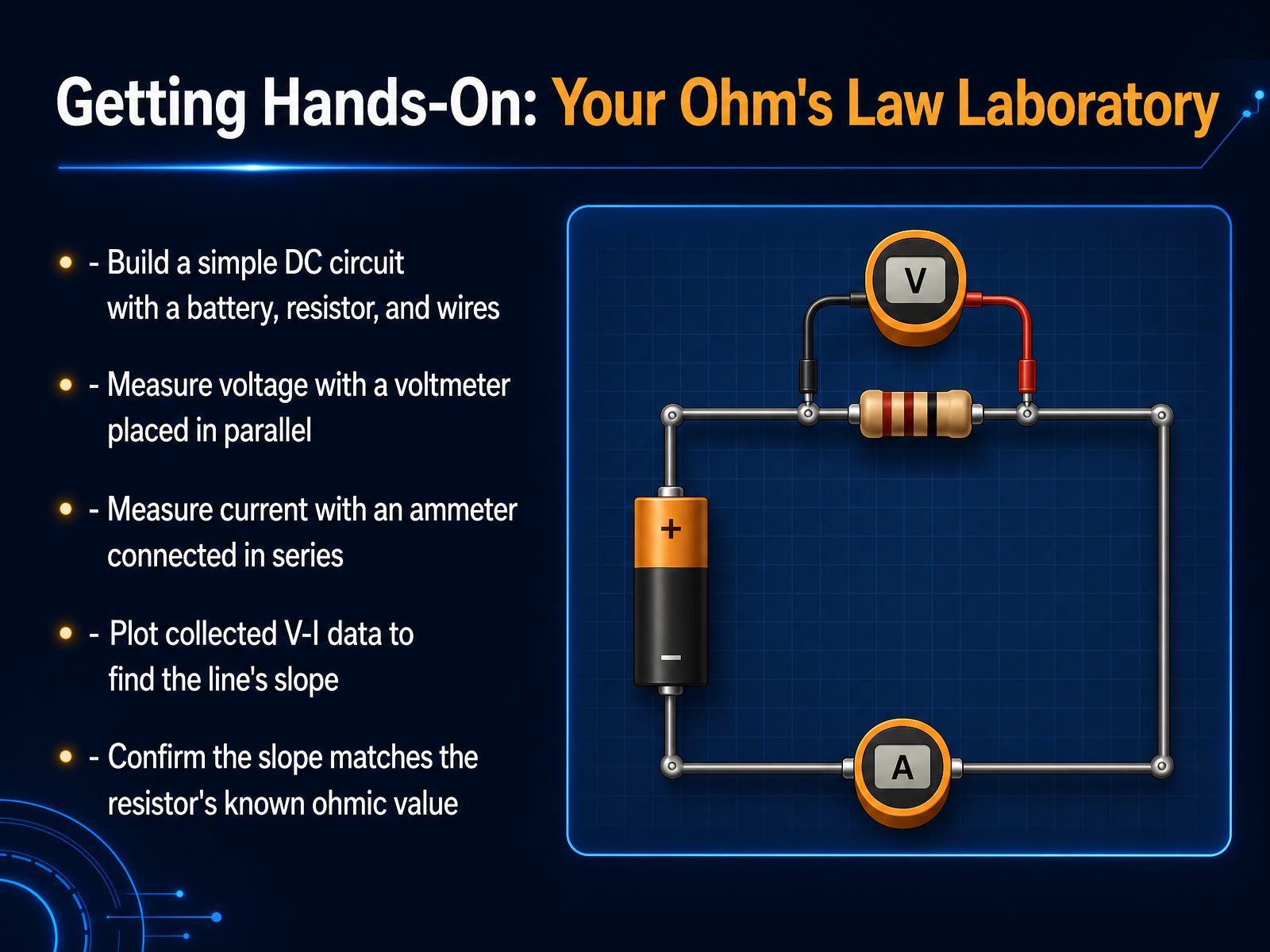
 - 08Getting Hands-On: Your Ohm's Law LaboratoryNow we're moving into our hands-on lab, where we can directly explore Ohm's Law. Let's build a simple DC circuit with a battery, a resistor, and connecting wires to form one complete loop. To see the electrical pressure, we'll measure voltage by placing a voltmeter in parallel with the resistor. To measure the rate of charge flow, we connect an ammeter in series, so all the current passes through it. Our goal is to vary the voltage and collect pairs of voltage and current data. When we plot these points on a graph, the data forms a straight line. The slope of this line is the circuit's resistance. If our resistor follows Ohm's Law, this calculated slope will match its known ohmic value perfectly. Next, we'll see what happens when we connect components into a single loop with series circuits, a single path for current.
 direct.physicsclassroom.comteachengineering.orgsepup.lawrencehallofscience.org+21 min
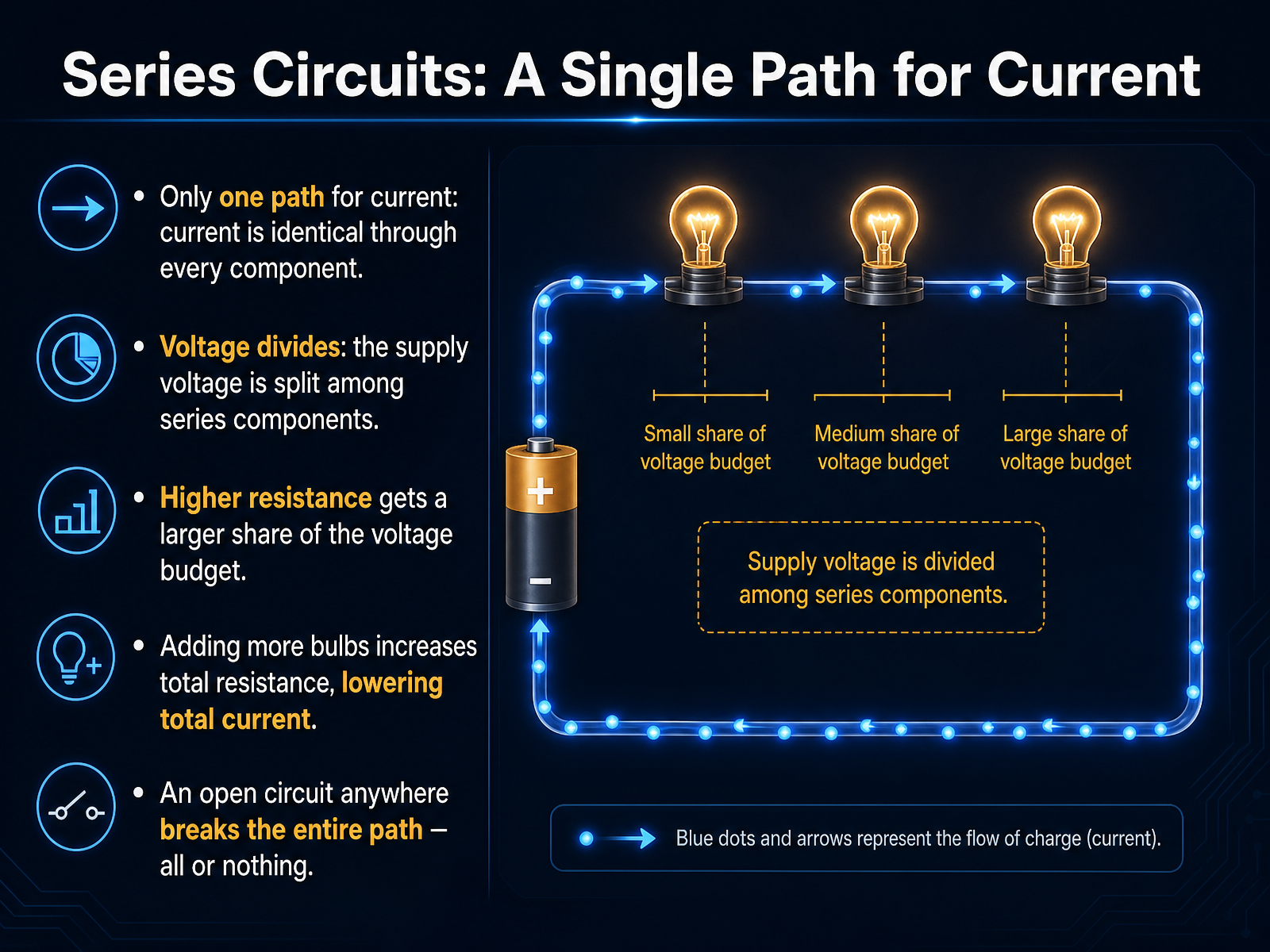
 - 09Series Circuits: A Single Path for CurrentNow let's look at a series circuit. Think of it as a single, unbroken loop. There is only one path for the current to travel, so the current is exactly the same through every component in that loop. The battery provides the driving force, which we call voltage. In a series circuit, this total voltage gets divided up among all the bulbs. Each bulb takes a share of the total voltage, so none of them gets the full amount. This is why adding more bulbs in series makes each one dimmer. A bulb with a higher resistance gets a larger share of the voltage, because it's harder to push the current through it. When you add more bulbs to the chain, you increase the total resistance of the circuit. Since the battery's push is fixed, more resistance means less overall current, and all the bulbs get even dimmer. And here's a crucial point about that single path: it's all or nothing. If you unscrew one bulb, or a wire breaks, the path is broken. The current stops everywhere instantly, and all the bulbs go out. Next, we'll contrast this with parallel circuits, which have multiple independent paths.
 2 min
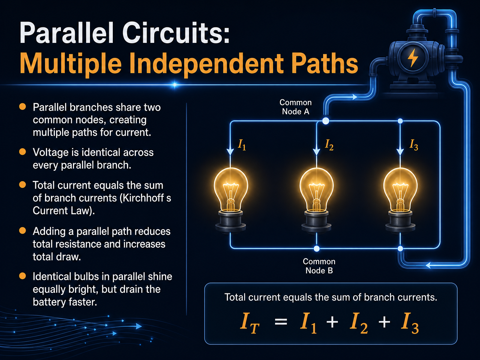
2 min - 10Parallel Circuits: Multiple Independent PathsNow let's look at parallel circuits, which give current multiple independent paths. Imagine a main water pipe splitting into two smaller pipes that later rejoin. The pressure from the main pump is felt equally at the start of both branches. In the same way, every parallel branch shares two common electrical nodes. The voltage across each branch is identical to the source voltage. Current divides among those branches based on the resistance in each path. The total current drawn from the battery is the sum of the branch currents. This is why adding another parallel path reduces the total resistance and increases the overall current draw. Think of identical light bulbs in parallel. Each bulb feels the full voltage, so each shines with the same brightness as a single bulb in a basic circuit. But because more current flows from the battery to feed all those branches, the battery drains faster. Now that you have a solid picture of parallel circuits, let's move on to diagnosing brightness and applying your model to real lamps.
 doi.orghyperphysics.gsu.edunpsm-kps.org+21 min
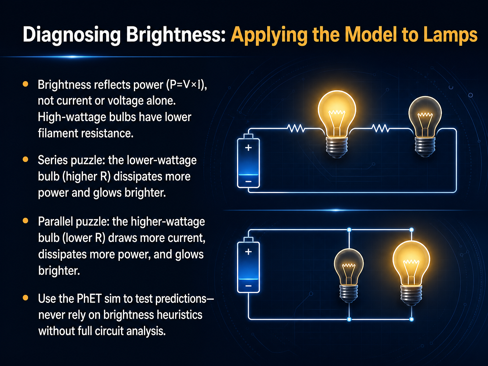
 - 11Diagnosing Brightness: Applying the Model to LampsNow let's apply our model to diagnose lamp brightness. Remember, brightness reflects power, which is voltage multiplied by current, not just current or voltage alone. A high-wattage bulb designed for standard voltage actually has lower filament resistance. With that in mind, let's examine two puzzles. In a series circuit, the bulbs share the same current. Here, the lower-wattage bulb has higher resistance and dissipates more power, so it glows brighter. In a parallel circuit, each branch receives the same voltage. Now the higher-wattage bulb has lower resistance, draws more current, dissipates more power, and glows brighter. See how the arrangement flips the result? To build your intuition, use the PhET simulation. Build these circuits, measure voltage, current, and watch how brightness changes. Never rely on brightness heuristics alone; always let a full circuit analysis guide you. Next, we'll build on this by exploring energy and power: where the circuit does work.
 2 min
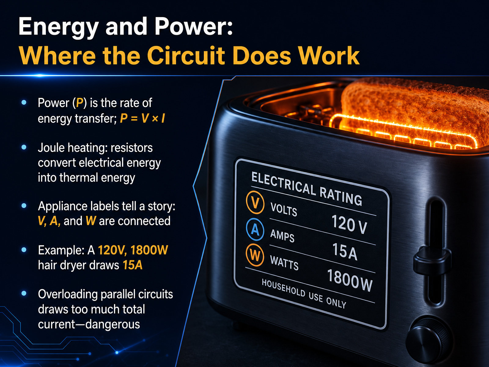
2 min - 12Energy and Power: Where the Circuit Does WorkNow let's talk about where a circuit actually does work: energy and power. Power, labeled P, is just the rate of energy transfer. You can calculate it with a simple equation: P equals V times I. So, a higher voltage pushing more current means more power is being delivered. A big part of this work is Joule heating. You've seen this already, when a resistor converts electrical energy into thermal energy. Think of a toaster glowing orange, that's resistance doing its job. Now, take a look at appliance labels. They tell a clear story. The voltage, current, and power numbers are all connected. For example, a 120-volt hair dryer rated at 1800 watts must draw 15 amps of current. You can see how the three pieces fit together perfectly. This idea also explains why overloading a circuit is dangerous. Plugging too many devices into one parallel circuit demands too much total current, which generates more heat than the wires can handle safely. So, understanding power gives you the full picture of how voltage, current, and resistance act together. Next, we'll move into troubleshooting and testing your mental model.
 direct.physicsclassroom.comteachengineering.orgsepup.lawrencehallofscience.org+22 min
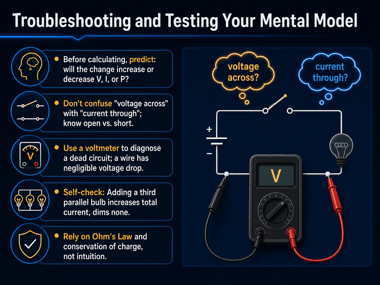
 - 13Troubleshooting and Testing Your Mental ModelNow it's time to troubleshoot and test your mental model. Before you calculate anything, pause and predict. If you change a part of the circuit, will the voltage, current, or power increase or decrease? This simple habit helps you catch mistakes early. One of the most common errors is confusing 'voltage across' a component with 'current through' it. Remember, an open circuit has voltage across the gap but no current. A short circuit has current flowing but negligible voltage drop. In fact, a plain wire in your circuit has almost zero voltage drop for that very reason. Let's do a self-check. Imagine you add a third identical bulb in parallel. The total current from the battery increases, but none of the bulbs dim. If your intuition said otherwise, don't worry. Many learners initially believe current gets used up or that the battery supplies a fixed amount. Instead, rely on Ohm's Law and the conservation of charge. These are your reliable guides, not gut feelings. Next, let's bring everything together with a summary, key takeaways, and your next steps.
 zybooks.comphysicsclassroom.comdoi.org+22 min
 - 14Summary, Key Takeaways, and Your Next StepsWe have covered a lot of ground together. Let's take a moment to review the key ideas and think about what comes next. First, and most importantly, a circuit must be a closed loop. The electric current is never used up or consumed; it simply flows in a continuous path. Second, think of voltage as the push that drives the current, while resistance is what limits that flow. This cause-and-effect relationship is captured beautifully by Ohm's Law, V equals I times R. This single equation is your bridge from a qualitative feel for circuits to making real, quantitative predictions. Third, the patterns you learned about series and parallel connections are not just isolated topics; they are the fundamental building blocks of every circuit you will ever see. And here is your next step: everything you have built here extends forward. The concepts of voltage, current, and resistance are the foundation for understanding more complex components like capacitors, semiconductors, and even the alternating current systems that power your home. Thank you for your focus and hard work. You now have a solid conceptual model to build on. Keep exploring, and remember, you can always trace a circuit back to these simple, powerful ideas.
 doi.orghyperphysics.gsu.edunpsm-kps.org+22 min
Take the deck with you
Download this course as a file — free, no sign-up needed.
- PDF handoutEvery slide page, ready to print or share.15 pages · 3.8 MBDownload
- Narrated PowerPointThe deck that presents itself — every slide carries the digital human's narration video.15 pages · 12.9 MBDownload
- PowerPoint slidesThe full deck as a .pptx — open it in PowerPoint, Keynote, or Google Slides.15 pages · 3.7 MBDownload
Free to use in your own training — please keep the PersonWise credit page at the end.
Have your own deck? Turn it into a course
Sources consulted
Web sources consulted while building this course.
- A Systematic Literature Review of Misconceptions in Linear Circuit Analysis — zybooks.com
- Common Misconceptions Regarding Electric Circuits — physicsclassroom.com
- A Systematic Review of Student Misconceptions about Electricity and Electric Circuit Concepts — doi.org
- Potential difference and current in simple electric circuits: A study of student’s concepts — per-central.org
- Physics Tutorial: Common Misconceptions Regarding Electric Circuits — physicsclassroom.com
- Teaching electric circuits with a focus on potential differences — doi.org
- Water circuit analogy to electric circuit — hyperphysics.gsu.edu
- Comparative Analysis of the Two Paradigms in the Hydraulic Analogy — npsm-kps.org
- Water Analogy to Electric Circuits | CHESS — chess.cornell.edu
- Water Model of Electricity - Clean Energy Institute — cei.washington.edu
- Electric current — en.wikipedia.org
- 9.1 Electrical Current - University Physics Volume 2 | OpenStax — openstax.org
- - ampere - BIPM — bipm.org
- 19.2: Microscopic model of current - Physics LibreTexts — phys.libretexts.org
- 20.1: Current - Physics LibreTexts — phys.libretexts.org
- Ohm's Law - Voltage, Current, and Resistance — direct.physicsclassroom.com
- Can You Resist This? - Activity - Teach Engineering — teachengineering.org
- DRAFT — sepup.lawrencehallofscience.org
- Get Connected With Ohm's Law - TryEngineering.org Powered by IEEE — tryengineering.org
- CSERD: Ohm's Law — shodor.org