Begin
14 pages · ~28 min
Electromagnetic Induction: Generating Electricity
This training explains electromagnetic induction and how generators convert motion into electricity, designed for learners seeking a foundational understanding of generator operation.
A digital instructor presents all 14 pages. Hold “Ask” at any point and ask out loud — the answer comes from this course. No sign-up needed.
What you’ll learn
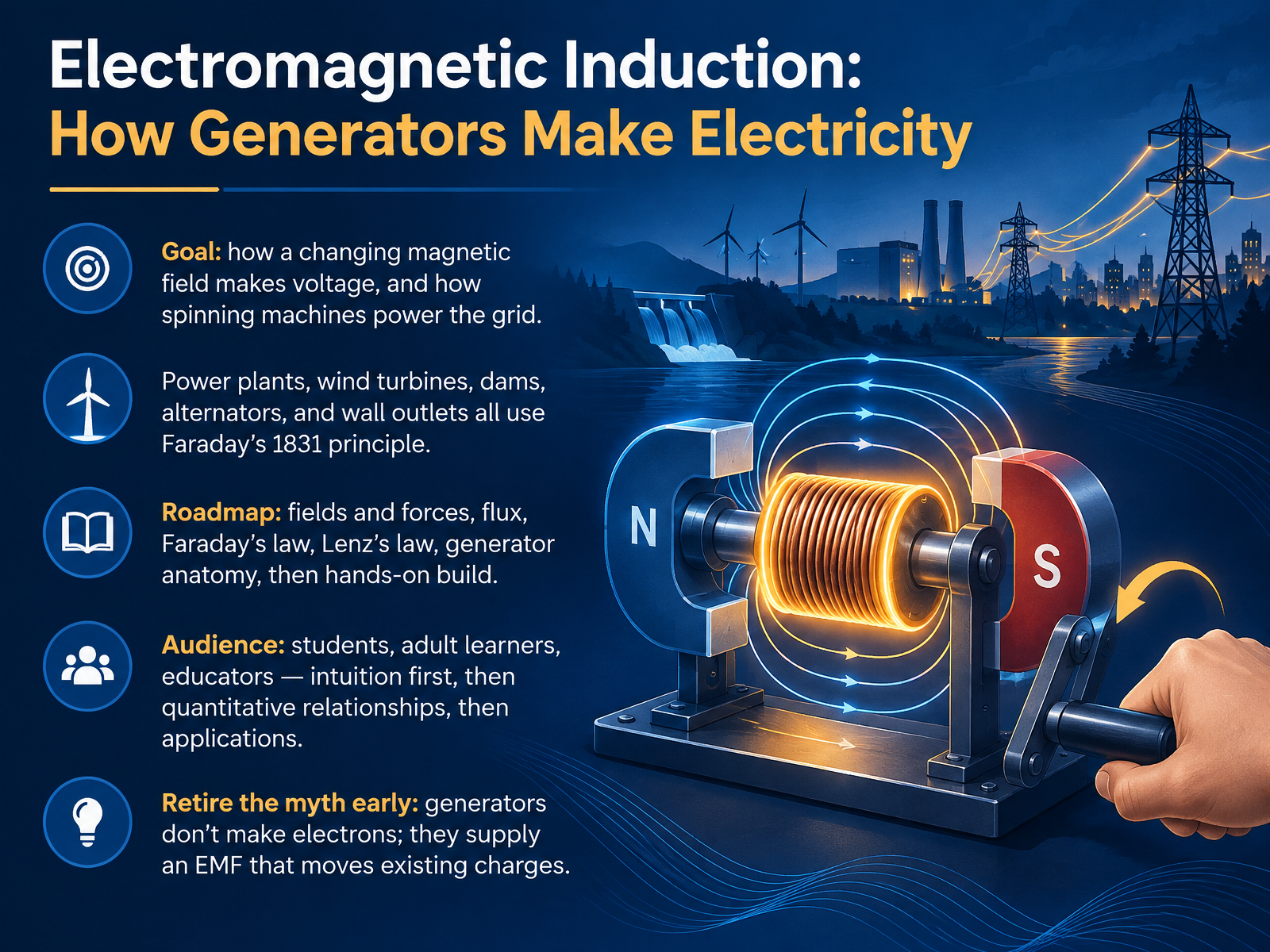
- 01Electromagnetic Induction: How Generators Make ElectricityWelcome. I'm glad you're here. Today we're exploring electromagnetic induction, the principle behind how generators make electricity. Our goal is simple. By the end, you'll understand how a changing magnetic field creates voltage, and how spinning machines power the grid. Power plants, wind turbines, dams, car alternators, and even the wall outlet in your room all trace back to Michael Faraday's discovery in eighteen thirty-one. We'll move in a clear order. First fields and forces, then magnetic flux, Faraday's law, Lenz's law, generator anatomy, and finally a hands-on build. Intuition first, then the quantitative relationships, then applications. And let's retire one myth early. Generators don't create electrons. They supply an electromotive force, or E M F, that moves charges already in the wire. That one idea will make everything else easier. Next, we'll look at magnetic fields, forces, and the generator effect.eia.govtechnav.ieee.orgbbc.co.uk+22 min
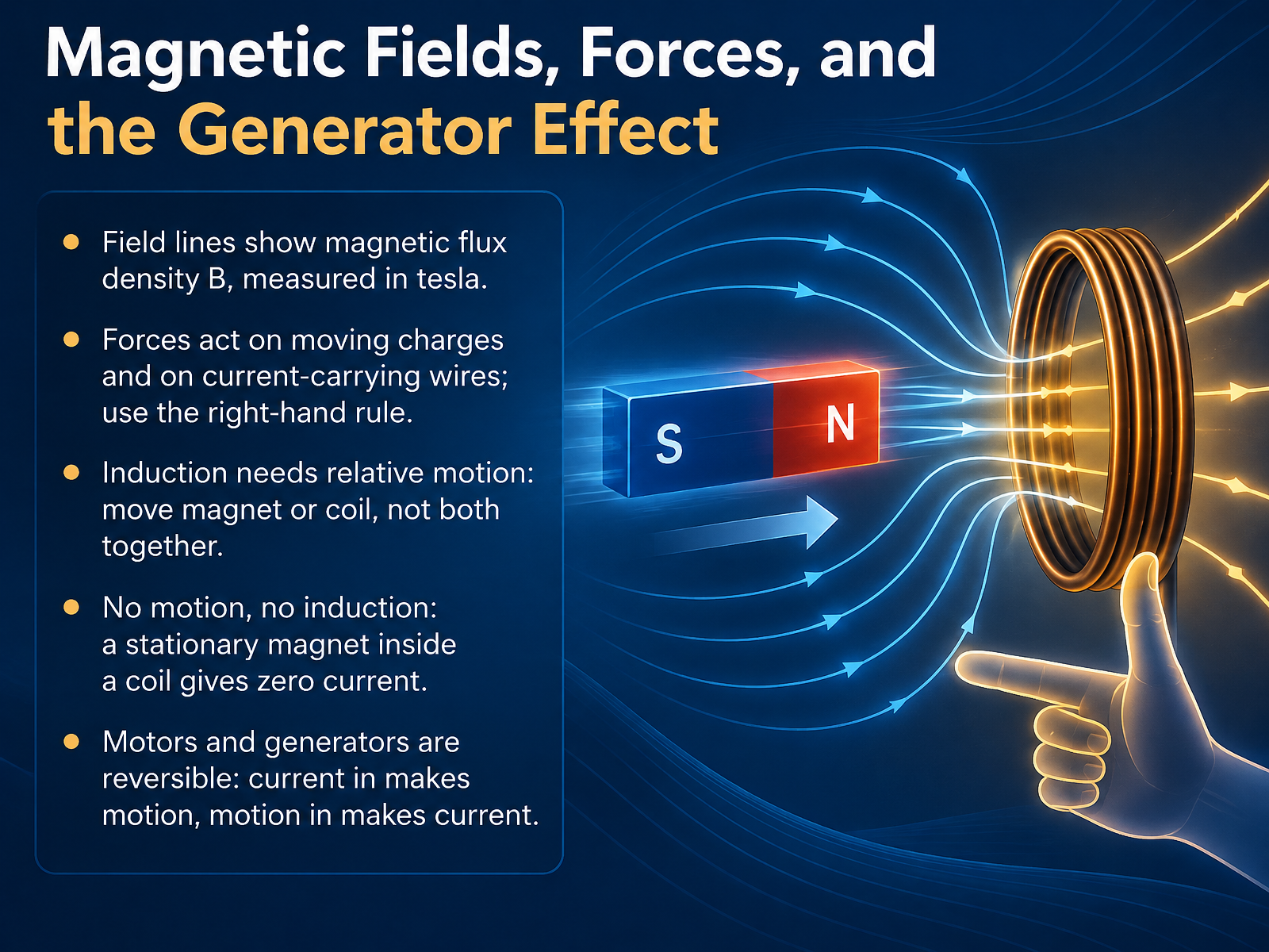
- 02Magnetic Fields, Forces, and the Generator EffectLet's look at the basic physics behind the generator effect. Field lines map out a magnetic field, and their density is called magnetic flux density, measured in tesla. Magnetic forces act on moving charges and on current-carrying wires, and the right-hand rule helps you predict their direction. For induction, what matters is relative motion. Move the magnet, or move the coil, but not both together. If nothing moves, nothing happens. A stationary magnet inside a coil produces zero current, even though the field is still there. And here is a useful idea: motors and generators are reversible. Feed current in, and you get motion. Put motion in, and you get current. To recap, induction requires change in motion or flux, not a magnetic field alone. Next, we will turn this geometry into a number, in Magnetic Flux: Turning Geometry into a Number.
 eia.govtechnav.ieee.orgbbc.co.uk+22 min
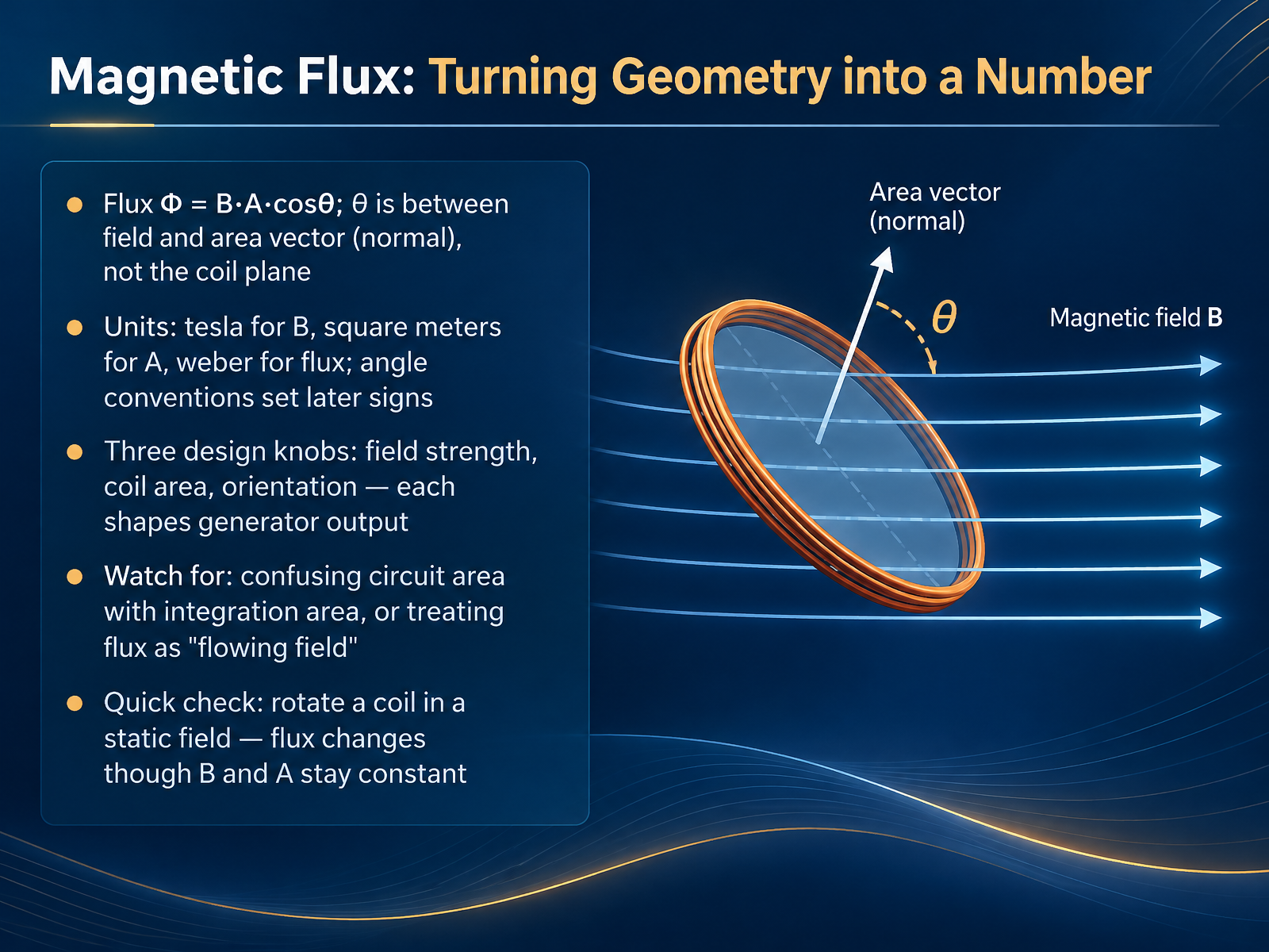
- 03Magnetic Flux: Turning Geometry into a NumberLet's take the idea of flux and turn it into a number. Magnetic flux measures how much magnetic field passes through a given area. On a flat coil, flux equals the field strength times the coil's area times the cosine of theta. Here theta is the angle between the magnetic field and the area vector, which points perpendicular to the coil's surface, not along the coil plane. That detail matters, and it sets the sign conventions you'll use later. The units follow directly. Field strength is in tesla, area in square meters, and flux in weber. Think of these as three design knobs: field strength, coil area, and orientation. Each one shapes generator output. Two cautions. Don't mix up the circuit area with the integration area, and don't picture flux as field flowing like water. Here's a quick check. Rotate a coil in a static field. The field and the area stay constant, but the flux changes, because the orientation changes. To wrap up: flux converts geometry into a single number, and rotation alone can change it. Next, we'll see how that change produces voltage in Faraday's Law: Induced Voltage from Changing Flux.
 openstax.orgopenstax.orgopenstax.org+22 min
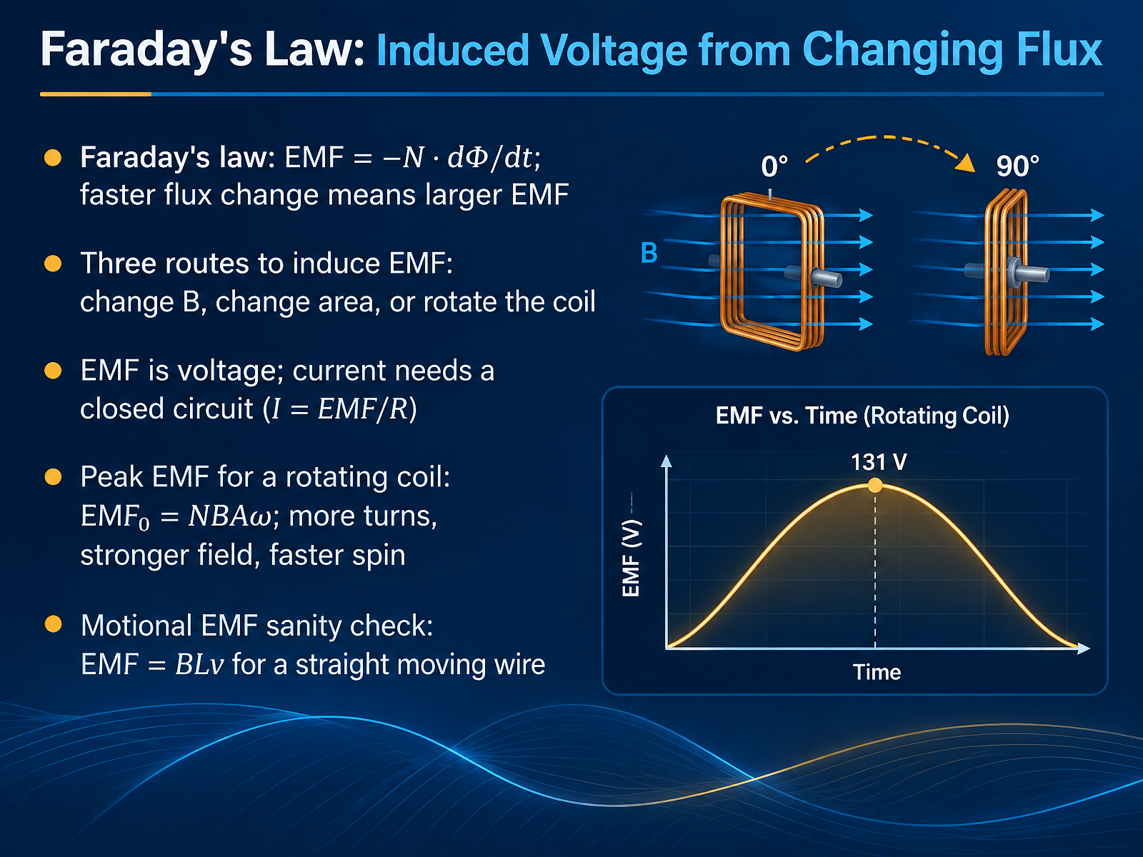
- 04Faraday's Law: Induced Voltage from Changing FluxNow we can write the idea down as Faraday's law. In words, the induced E M F equals negative N times the rate of change of magnetic flux. N is the number of turns in the coil. Flux is the amount of magnetic field passing through the coil's area. The key word is change. A steady field induces nothing. A faster change in flux gives a larger E M F. That gives three routes to induction. Change the magnetic field strength, change the area the field passes through, or rotate the coil. One caution: E M F is a voltage, not a current. Current needs a closed circuit, where current equals E M F divided by resistance. For a rotating coil, peak E M F equals N times B times A times omega. So more turns, a stronger field, a larger coil, or a faster spin all raise the voltage. As a sanity check, a straight wire of length L moving at speed v across a field produces an E M F of B times L times v. Keep the takeaway: changing flux is what matters, and the faster it changes, the bigger the voltage. Next, we look at direction and energy with Lenz's Law and Energy Conservation.
 openstax.orgopenstax.orgopenstax.org+22 min
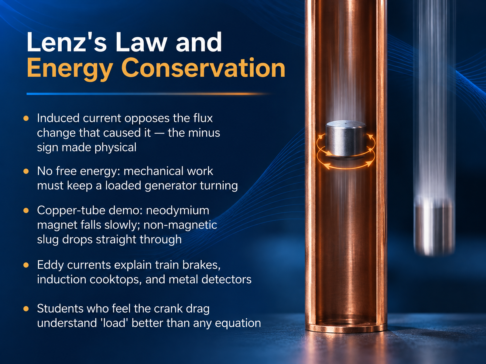
- 05Lenz's Law and Energy ConservationNow let's look at the direction of that induced current, which brings us to Lenz's Law. In Faraday's law, there's a minus sign in front of the flux change. Lenz's Law makes that minus sign physical. The induced current always flows in the direction that opposes the very change in magnetic flux that created it. This is not a quirk of the math. It is energy conservation in action. A loaded generator always resists being turned, so mechanical work must keep feeding it. That's why there's no free energy. A classic demonstration makes this vivid. Drop a strong neodymium magnet down a copper tube, and it falls slowly, taking many seconds. A non-magnetic slug of the same size drops straight through in under a second. The moving magnet induces swirling eddy currents in the copper, and those currents create a magnetic field that pushes back. The same effect gives us eddy current brakes on trains, induction cooktops, and metal detectors. And students who feel the crank drag when a generator is loaded understand load better than any equation. So remember, induced current opposes change, and that opposition is what keeps energy honest. Next, we move inside a generator to look at the rotor, the stator, and the prime movers that spin them.
 physicslabs.colorado.eduinstructional-resources.physics.uiowa.edusfu.ca+22 min
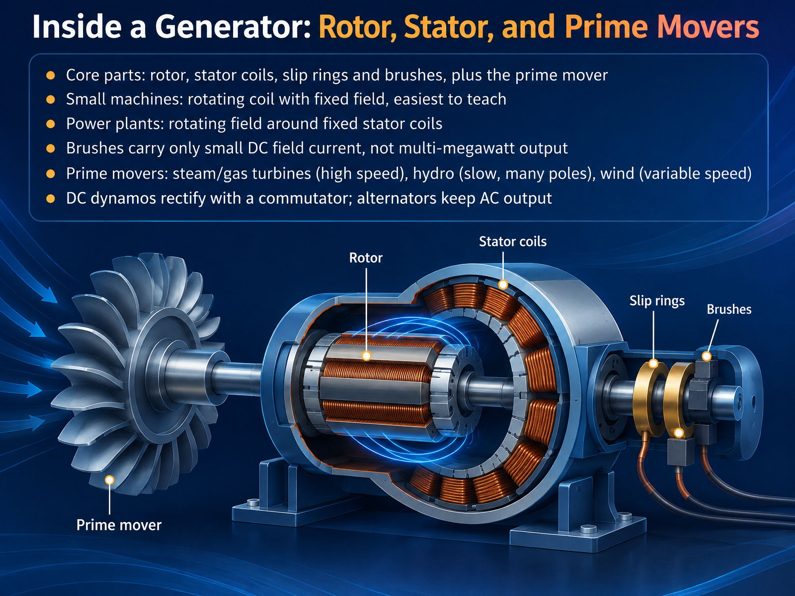
- 06Inside a Generator: Rotor, Stator, and Prime MoversNow let's look inside a real generator. The main parts are the rotor, the spinning member, the stator, the stationary frame that holds the output coils, and the prime mover, the turbine or engine that turns the shaft. In small teaching machines, a coil rotates inside a fixed magnetic field. That is the easiest design to understand. In power plants, the arrangement is reversed. The magnetic field rotates on the rotor, and the output coils sit still in the stator. Here is the key point. Slip rings and brushes carry only a small direct current to energize the field, not the multi-megawatt output. The prime mover matters too. Steam and gas turbines spin fast. Hydro turbines turn slowly with many poles. Wind turbines change speed with the wind. A direct current dynamo uses a commutator to rectify its output, while an alternator keeps alternating current. So remember, the rotor makes the field, the stator makes the power, and the prime mover supplies the motion. Next, we move from sine waves to the grid, looking at frequency and three-phase output.
 nrc.govhome.engineering.iastate.edugeosci.uchicago.edu+22 min
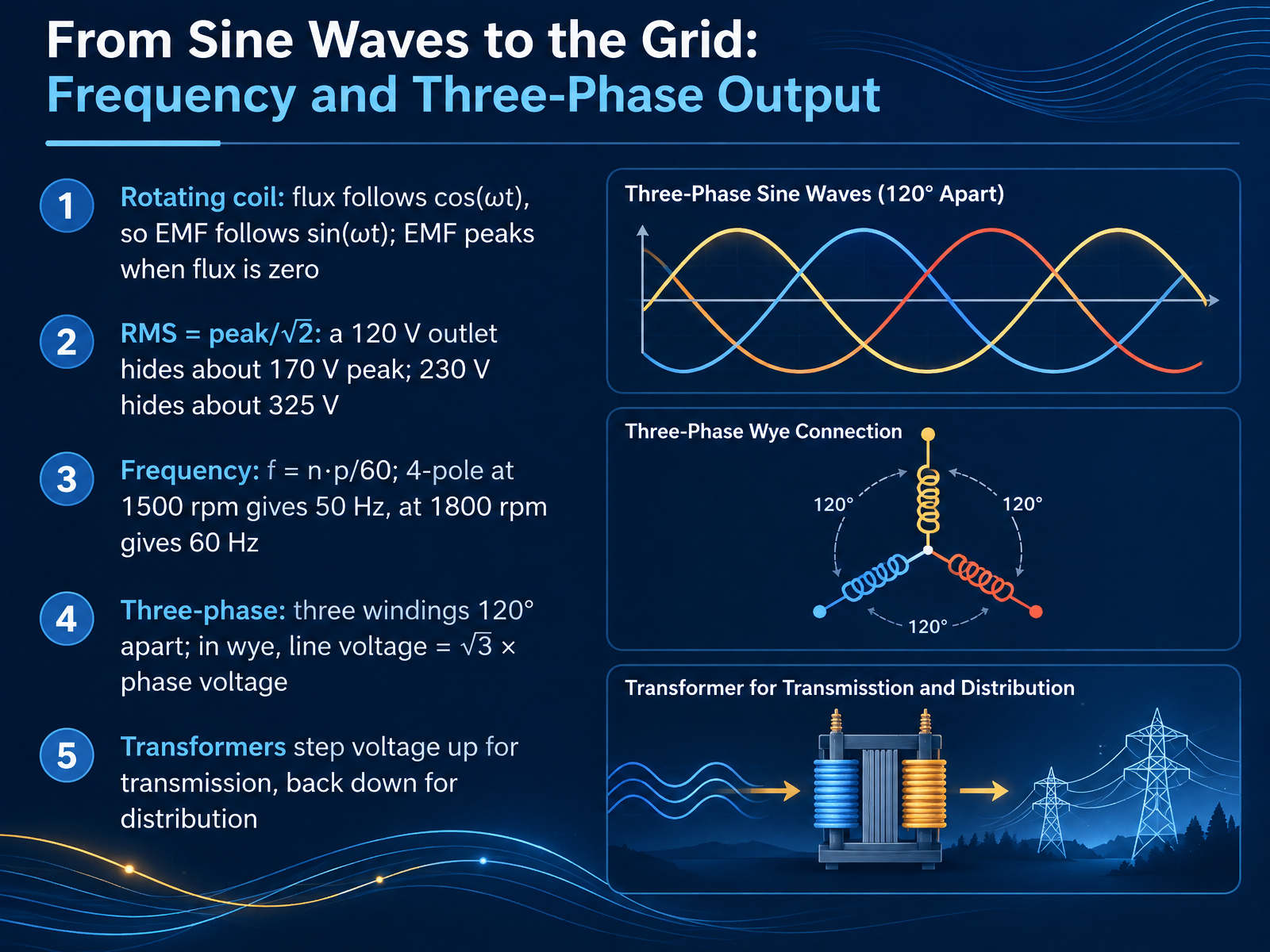
- 07From Sine Waves to the Grid: Frequency and Three-Phase OutputSo let's follow that sine wave all the way to the grid. In a rotating coil, the magnetic flux follows a cosine curve, so the induced EMF follows a sine curve. Notice this counterintuitive point: the voltage peaks when the flux is zero, because that is when the flux is changing fastest. Now, the voltage we quote is an average-like figure called RMS, root mean square. RMS equals peak divided by the square root of two. So your one hundred twenty volt outlet actually peaks near one hundred seventy volts, and two hundred thirty volts hides about three hundred twenty five volts of peak. Frequency depends on speed and pole count: f equals n times p divided by sixty. A four-pole machine gives fifty hertz at fifteen hundred revolutions per minute, and sixty hertz at eighteen hundred. For three-phase output, three windings sit one hundred twenty degrees apart. In a wye connection, line voltage is square root of three times phase voltage. Finally, transformers step voltage up for transmission and back down for distribution. In short: sine waves, RMS values, frequency, and three phases. Next, we look at losses, efficiency, and voltage control.
 openstax.orgopenstax.orgopenstax.org+22 min
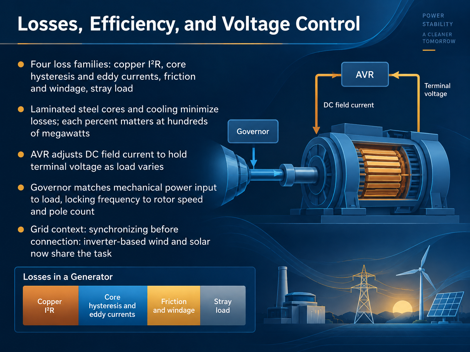
- 08Losses, Efficiency, and Voltage ControlNow let's talk about where the energy goes, and how we keep voltage steady. Losses come in four families. Copper loss, written as I squared R, is heating in the windings because they carry current. Core loss comes from hysteresis and eddy currents in the steel. Friction and windage is mechanical drag from bearings and cooling air. And stray load loss covers the smaller effects that don't fit neatly elsewhere. Laminated steel cores and cooling reduce these losses, and at hundreds of megawatts, every percent matters. On the control side, the automatic voltage regulator, or AVR, adjusts the DC field current to hold terminal voltage steady as load varies. The governor does a different job. It matches mechanical power input to the load, which locks frequency to rotor speed and pole count. On the grid, a generator must be synchronized before connection. And today, inverter based wind and solar share that voltage and frequency task. So remember: manage losses, and use the AVR and governor to hold voltage and frequency. Next, we move from theory to practice in Hands-On Build: A Classroom Generator.
 nrc.govhome.engineering.iastate.edugeosci.uchicago.edu+22 min
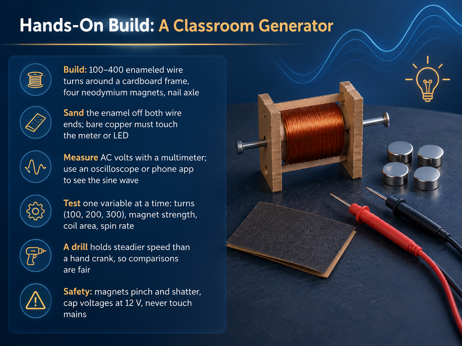
- 09Hands-On Build: A Classroom GeneratorNow let's build one. Wrap one hundred to four hundred turns of enameled wire around a cardboard frame, meaning copper wire coated in a thin insulating layer. Add four neodymium magnets, which are very strong permanent magnets, on a nail axle. Sand the enamel off both wire ends until bare copper shows, because only bare copper touches the meter or LED. Then measure AC volts with a multimeter, or watch the sine wave on an oscilloscope or a phone app. Test one variable at a time: turns, magnet strength, coil area, or spin rate. Use a drill for steadier speed so comparisons are fair. Finally, safety. Magnets pinch and shatter, cap voltages at twelve volts, and never touch mains. Next, we'll troubleshoot the build and read the output.
 physicslabs.colorado.eduinstructional-resources.physics.uiowa.edusfu.ca+21 min
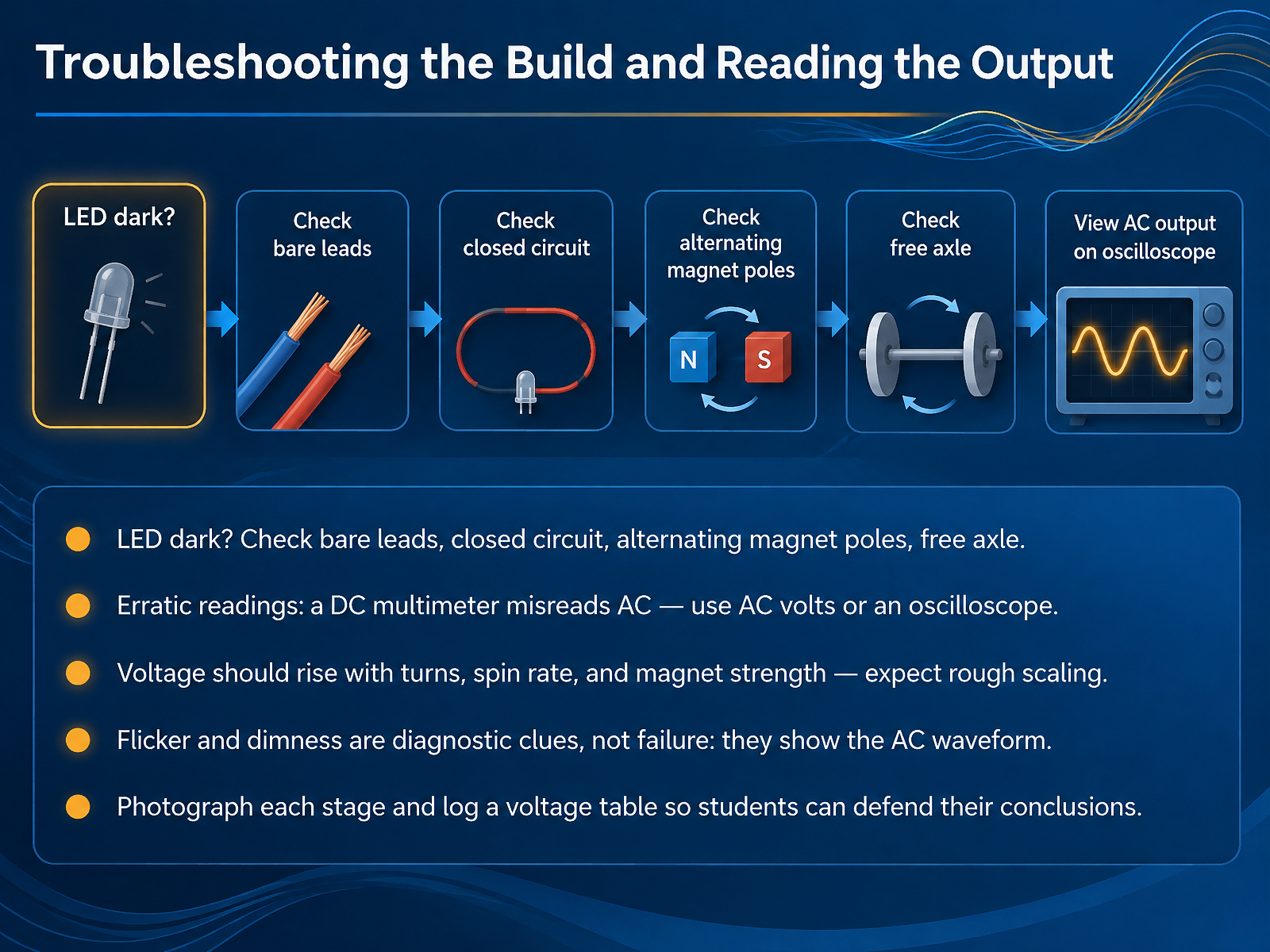
- 10Troubleshooting the Build and Reading the OutputNow that your generator is built, let us troubleshoot it and learn to read what it tells you. If the LED stays dark, check four things. First, are the leads actually bare, with the enamel sanded off? Second, is the circuit truly closed? Third, do the magnet poles alternate as they face outward, so the field reverses each half turn? And fourth, does the axle spin freely? If your meter jumps around erratically, that is a clue, not a fault. A DC setting misreads AC, so switch to AC volts, or watch the waveform on an oscilloscope. Voltage should rise with more turns, faster spin, and stronger magnets. Expect rough scaling, not exact numbers. Flicker and dimness are diagnostic clues too, because they reveal the alternating waveform itself. Finally, photograph each build stage and log a voltage table. That record is how you defend your conclusions. So: check the basics, measure in AC, and write everything down. Next, we look at teaching sequence: phenomenon first, then model, then math.
 physicslabs.colorado.eduinstructional-resources.physics.uiowa.edusfu.ca+22 min
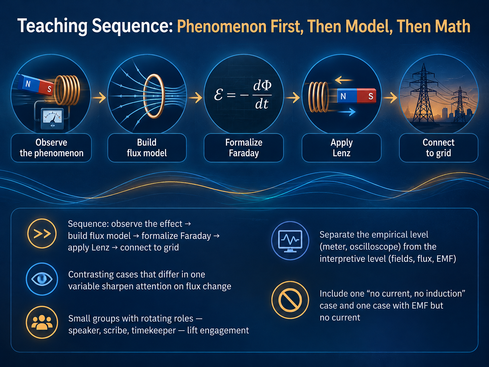
- 11Teaching Sequence: Phenomenon First, Then Model, Then MathNow let's talk about how to actually teach this, step by step. Start with the phenomenon. Students observe the effect first, seeing a meter or an oscilloscope respond, before you name any terms. Then you build the flux model, formalize Faraday's law, apply Lenz's law, and finally connect it all to the power grid. Contrasting cases help here. Change one variable at a time, and attention sharpens on what really matters: a change in magnetic flux. In small groups, have students rotate roles as speaker, scribe, and timekeeper to keep everyone engaged. And keep two levels separate: the empirical level, what the meter shows, and the interpretive level of fields, flux, and electromotive force. Include one case with no current and no induction, and one case with an electromotive force but no current. That second case is where many students stumble. Let's move on to common misconceptions and how to correct them.
 nrc.govhome.engineering.iastate.edugeosci.uchicago.edu+22 min
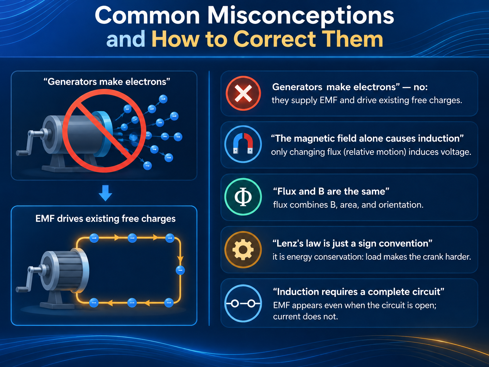
- 12Common Misconceptions and How to Correct ThemLet's clear up some common misconceptions about induction. First, generators do not create electrons. The electrons are already in the wire. A generator supplies an electromotive force, or E M F, which pushes those existing charges into motion. Second, the magnetic field alone does not cause induction. What matters is changing flux, meaning relative motion between the field and the circuit. Hold a magnet still inside a coil and nothing happens. Third, flux and magnetic field are not the same. Flux combines the field strength, the area of the loop, and the orientation between them. Fourth, Lenz's law is not just a sign rule. It is energy conservation. When your generator powers a load, the crank gets harder to turn. Finally, induction does not require a closed circuit. An E M F appears even with open terminals. Current only flows when the circuit is complete. So remember: changing flux creates voltage, and energy is conserved. Where Induction Shows Up: Applications and Extensions.
 openstax.orgopenstax.orgopenstax.org+22 min
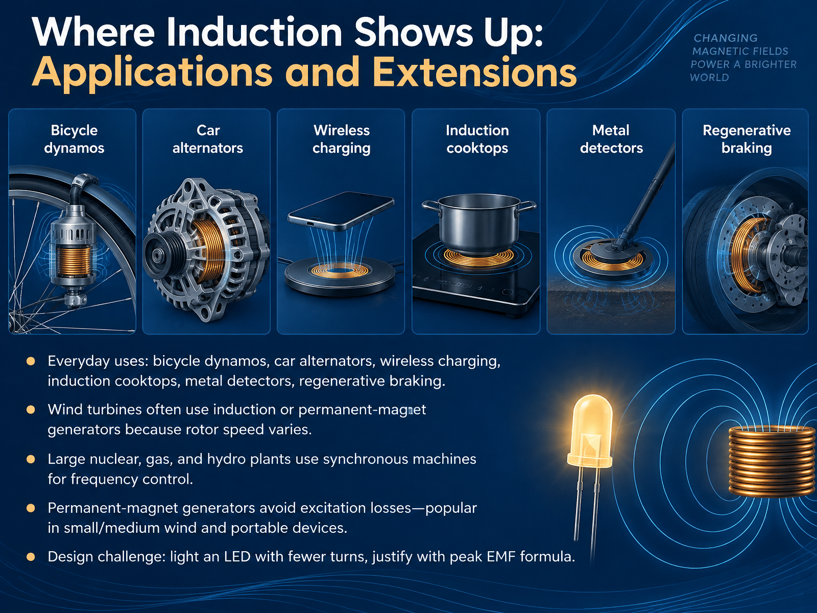
- 13Where Induction Shows Up: Applications and ExtensionsLet's bring induction into the real world. You already rely on it every day. A bicycle dynamo, a car alternator, wireless charging, an induction cooktop, a metal detector, and the regenerative braking in electric vehicles all depend on changing magnetic flux. Wind turbines often use induction or permanent-magnet generators, because rotor speed varies with the wind. Large nuclear, gas, and hydro plants use synchronous machines, because their output frequency can be tightly controlled. Permanent-magnet generators avoid the losses of an electrical excitation system, which is why they are popular in small and medium wind turbines and portable devices. Here is a design challenge. Suppose you need to light an LED with fewer coil turns. Can you justify that with the peak EMF formula? The peak EMF equals the number of turns times the magnetic flux times the angular frequency. Fewer turns means you must compensate with stronger magnets or faster rotation. So when you test your design, ask whether the trade-off holds for real. In short, induction scales from a dynamo to a power plant, and the same few variables drive every design decision. Next, we will check your understanding with a short assessment and wrap-up.
 2 min
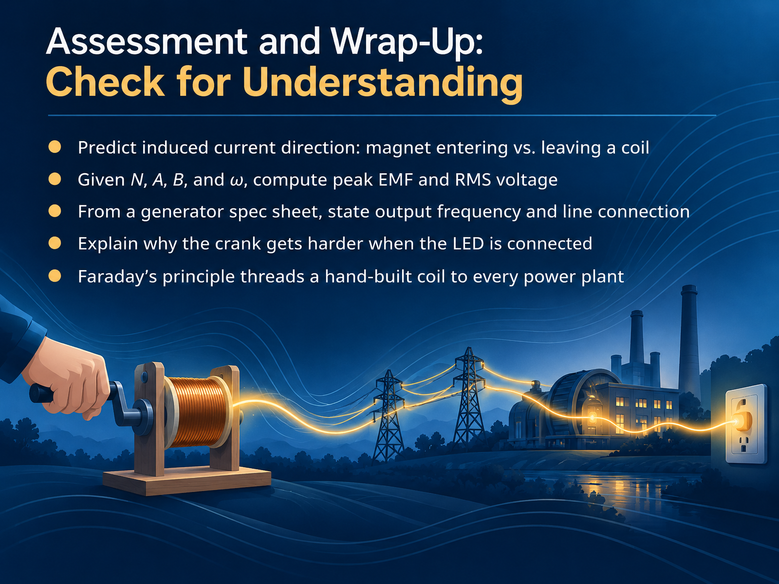
- 14Assessment and Wrap-Up: Check for UnderstandingLet's close by checking your understanding. First, can you predict the induced current's direction when a magnet enters a coil, and how it reverses when the magnet leaves? Remember, Lenz's law says the induced current opposes the change in flux. Second, given the number of turns, area, magnetic field, and angular speed, compute the peak E M F as N times A times B times omega, then divide by the square root of two for R M S voltage. Third, from a generator spec sheet, state the output frequency and whether the coils are wye or delta connected. Fourth, explain why the crank gets harder when the L E D is connected. The connected load draws current, and that current creates a magnetic force that opposes the rotation. That is energy conversion, not friction. Finally, remember that Faraday's principle threads through everything from your hand-built coil to every power plant on the grid. Thank you for working through this material. Keep asking how the change in flux drives the current, and you will keep seeing it everywhere.
 openstax.orgopenstax.orgopenstax.org+22 min
Take the deck with you
Download this course as a file — free, no sign-up needed.
- PDF handoutEvery slide page, ready to print or share.15 pages · 4.2 MBDownload
- Narrated PowerPointThe deck that presents itself — every slide carries the digital human's narration video.15 pages · 16.2 MBDownload
- PowerPoint slidesThe full deck as a .pptx — open it in PowerPoint, Keynote, or Google Slides.15 pages · 4.1 MBDownload
Free to use in your own training — please keep the PersonWise credit page at the end.
Have your own deck? Turn it into a course
Sources consulted
Web sources consulted while building this course.
- How electricity is generated - U.S. Energy Information Administration (EIA) — eia.gov
- Electric generators | IEEE Technology Navigator — technav.ieee.org
- The AC generator - CCEA — bbc.co.uk
- Electromagnetic Generator - an overview | ScienceDirect Topics — sciencedirect.com
- Induced potential and the generator effect - What is the process inside an electric generator? - Higher - GCSE Physics (Single Science) Revision - OCR 21st Century - BBC Bitesize — bbc.co.uk
- 13.6 Electric Generators and Back Emf - University Physics Volume 2 | OpenStax — openstax.org
- 23.5 Electric Generators - College Physics | OpenStax — openstax.org
- 13.3 Motional Emf - University Physics Volume 2 | OpenStax — openstax.org
- FARADAY'S LAW and THE AC GENERATOR — faraday.physics.utoronto.ca
- Since the angle θ in eq. (1) for the magnetic flux depends on time, the flux itself depends on time as — web2.ph.utexas.edu
- Eddy Currents: Copper Tube - Physics Demonstrations - Eddy Currents: Copper Tube | Physics Undergraduate Labs | University of Colorado Boulder — physicslabs.colorado.edu
- 5K20.25 - Lenz's Law - Tubes and Magnets | Instructional Resources and Lecture Demonstrations - Department of Physics & Astronomy | The University of Iowa — instructional-resources.physics.uiowa.edu
- 5K20.25 Eddy Current Tubes - Demonstrations - Simon Fraser University — sfu.ca
- Electromagnetic braking in a copper pipe — spark.iop.org
- Eddy Current Tubes | Idaho State University — isu.edu
- Training Material for E-111 Emergency Diesel Generator Course, Power Point Chapter 09 (5-18), The Generator, Exciter & Voltage Regulator — nrc.gov
- Synchronous Machines 1.0 Introduction One might easily argue that the synchronous generator is the most important component in the power system, since synchronous generators Are the source of 99% of the MW in most power systems; Provide frequency regulation and load following; Are the main source of — home.engineering.iastate.edu
- THEORY, CONSTRUCTION, AND OPERATION — geosci.uchicago.edu
- Synchronous Generator | Working Principle, Types | Electrical Academia — electricalacademia.com
- Synchronous machines (generator and motor) in a nutshell | EEP — electrical-engineering-portal.com